A patented alternative to the four-link mechanism
Gene Bachman's patented linkage system reproduces a controlled motion path using a three-link, three-pivot configuration — fewer parts than the conventional four-link mechanisms built into countless tools and machines.
Rethinking a common mechanism class
Four-link mechanisms are built into countless tools and machines. The patented linkage concept explores whether selected quadrilateral arrangements can be reconfigured into a three-link system while preserving or modifying the required motion path.
Said plainly: it's a three-link, path-guided linkage — a base link with a fixed pivot and a non-linear (typically arcuate) path, a support link, and a follower link that tracks that path. Per the patent's own abstract, the intent is a simpler design that reduces weight, complexity, and space requirements compared to the four-link mechanism it replaces.
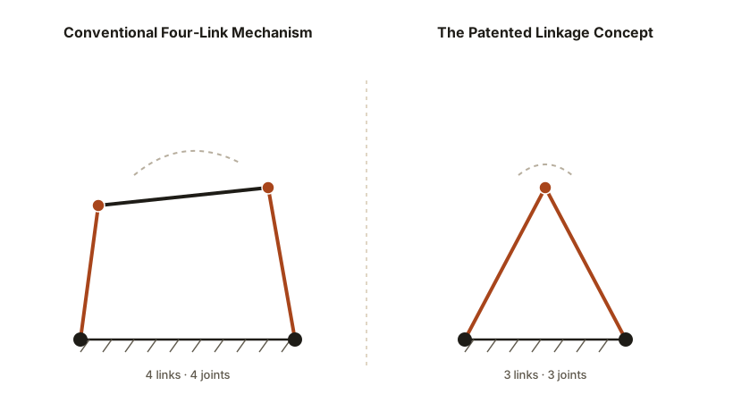
The patent's independent claim describes this three-link structure directly — see it on the Inventor and Patents page, alongside drawings applying it to a basketball hoop mount, a vehicle seat, a camera mount, a robotic arm, and a scissors mechanism. The claim describes the linkage structure itself rather than any one of those products, which is why other four-link products (see Applications) may be worth evaluating too — though whether a specific product falls within the patent's claims is a legal question, not something decided on this website.
The prosthetic-knee reference case
Many mechanical joints — from prosthetic knees to suspension linkages — rely on a chain of connected links and pivot points to guide part of an assembly through a specific path of motion. Gene Bachman's reference point during development has been a six-link mechanism used in existing prosthetic-knee designs.
The patented linkage concept is intended to produce a comparable, controlled motion path using a smaller number of links and pivots. Reducing the link count is the central engineering idea being tested — the goal is a simpler mechanical assembly that may also weigh less and take up less space.
This is a concept and prototype-stage design, not a finished or validated product. It has not been clinically tested, medically approved, certified, or confirmed as production-ready.
Linkage Motion Model
3D view unavailable in this browser.
Reference materials (pending release)
The items below are placeholders. Actual CAD files, diagrams, prototype photography, and video will be added once approved for public release.
CAD Drawing
Awaiting an approved CAD export.
Linkage-Motion Diagram
Awaiting an approved motion-path diagram.
Prototype Photograph
Awaiting an approved photo of the 3D-printed prototype.
Demonstration Video
Awaiting an approved short demonstration video of the mechanism in motion.
Interactive 3D Model (Spline)
No Spline scene exists yet. Once one is built (e.g. a detailed 3D render of the prototype), embed it by adding the snippet below — with the real scene URL — to this page.
<script type="module" async
  src="https://unpkg.com/@splinetool/viewer@1.9.x/build/spline-viewer.js"></script>
<spline-viewer
  url="https://prod.spline.design/REPLACE-WITH-SCENE-ID/scene.splinecode">
</spline-viewer>
Pin an exact version (not @latest) before publishing, and caption the embed the same way as other technical media on this page once it goes live.
Inventor-reported figures, not yet independently verified
The figures below reflect Gene Bachman's current development targets and comparisons to the six-link reference mechanism he has studied. They are goals for the design, not measured or certified results, and have not been independently verified by a third party.
Inventor-reported target
Inventor-reported comparison
Inventor-reported target
Proof points still needed
Stronger marketing language — words like "superior," "proven," or "more efficient" — would require the evidence below. None of it exists yet, so none of those words are used on this site. This list is an honest roadmap for manufacturers evaluating where the project actually stands.
- Patent numbers & inventorship — verified: US 10,328,822 & US 11,059,395 Available
- Legal claim-scope opinion (does it cover a given product?) Not yet available
- Conventional four-link mechanism comparison Not yet available
- Prototype, independently tested & documented Not yet available
- Part-count comparison Not yet available
- Measured weight comparison Not yet available
- Measured range-of-motion data Not yet available
- Required input-force comparison Not yet available
- Load & fatigue testing Not yet available
- Manufacturing-cost estimate Not yet available
- Video demonstrating both mechanisms side by side Not yet available
- Independent engineering review Not yet available
Want to review the engineering in more depth?
Next EV To Do can walk qualified engineers and manufacturing partners through the current design under an appropriate level of confidentiality.